Grab and Go: Control a Robotic Claw Arm with Push Buttons and Arduino
For this tutorial, I’ll be demonstrating how to put together and control a simple robotic claw arm using Arduino and a few push buttons. To start you’ll need to gather your supplies and I also recommend making sure that all of your components work. The list below includes everything you’ll need as well as a link for where each component can be purchased, if you do not have everything already.
Supplies:
x1 Arduino Board (For this tutorial, I’ll be using an Arduino Mega2560)
x6 Push Buttons
Breadboard Jumper Wires (Male to Male)
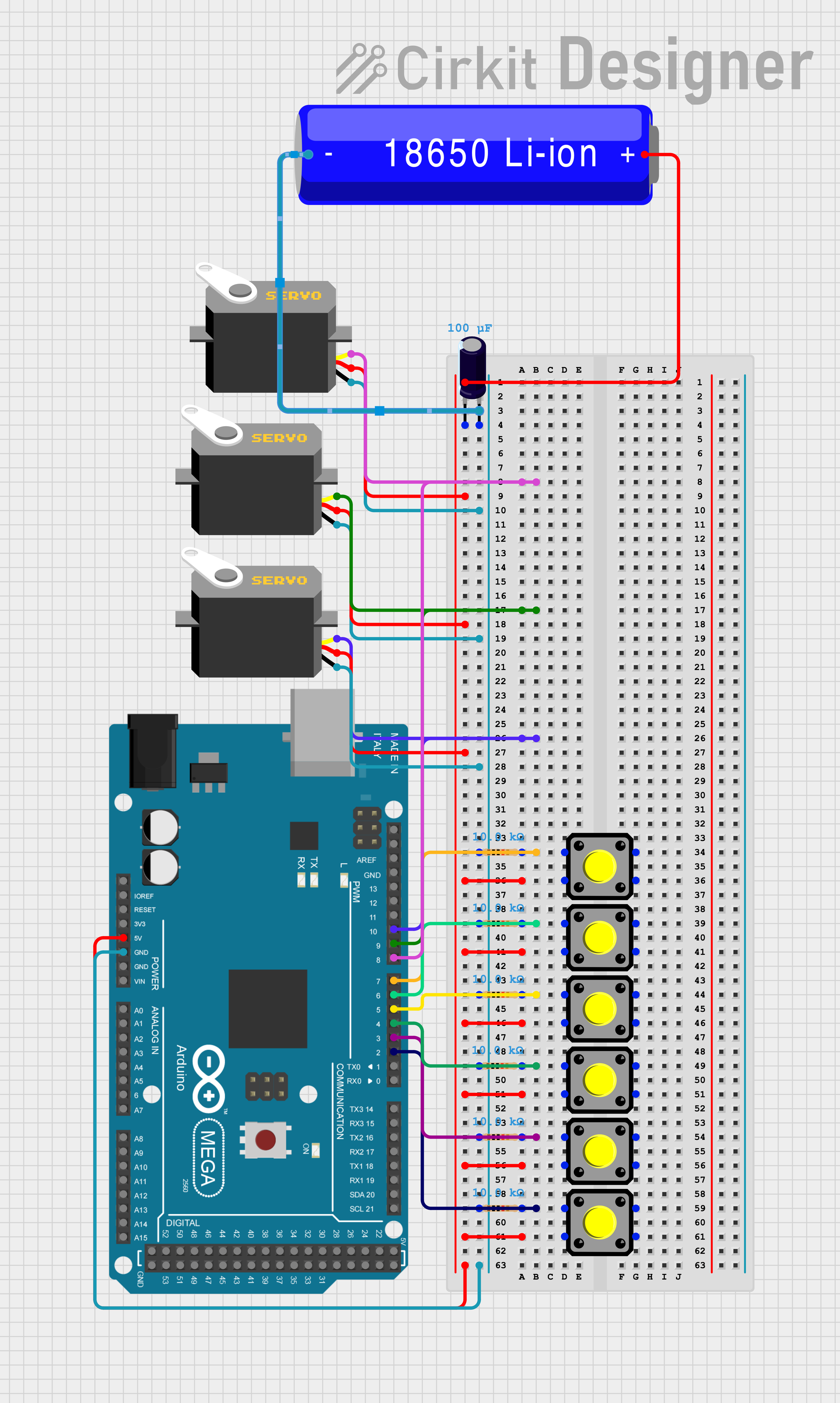
Once you’ve gathered all of your supplies, it’s time to start putting componentst together. The first thing we’ll want to do is to add the push buttons to the breadboard. Depending on what type of push buttons you have, the easiest way to do this will likely be by starting at one end of the breadboard and placing them in a line, down the center of the breadboard. The image below will provide more detail.
Note: the buttons should be placed so the pins are out to the sides vs top and bottom as this ensures that you can properly connect them
Once you have your buttons placed in suitable spots on the breadboard, the next step will be to connect them to the breadboard ground and power supply and to the Arduino board so they can be interacted with. So from here, you’ll want to add a 10K Ohm resistor to one of the pins for each button and connect that same resistor to the ground bus on your breadboard. From there, you’ll connect the other pin to the power bus.
Once you’ve successfully added these connections, start with the button at the bottom of the breadboard and add a wire in one of the pins between the 10K Ohm resistor and the button’s pin. Connect that same wire to the 2 pin on the Arduino. Move on to the next button in line and connect that one to the 3 pin. The one after that will connect to the 4 pin. After that will be the 5 pin, then the 6 pin and finally, connect the last button in the line, to the 7 pin.
Now that you have all of your buttons connected and ready to go, it’s time to add the servos.
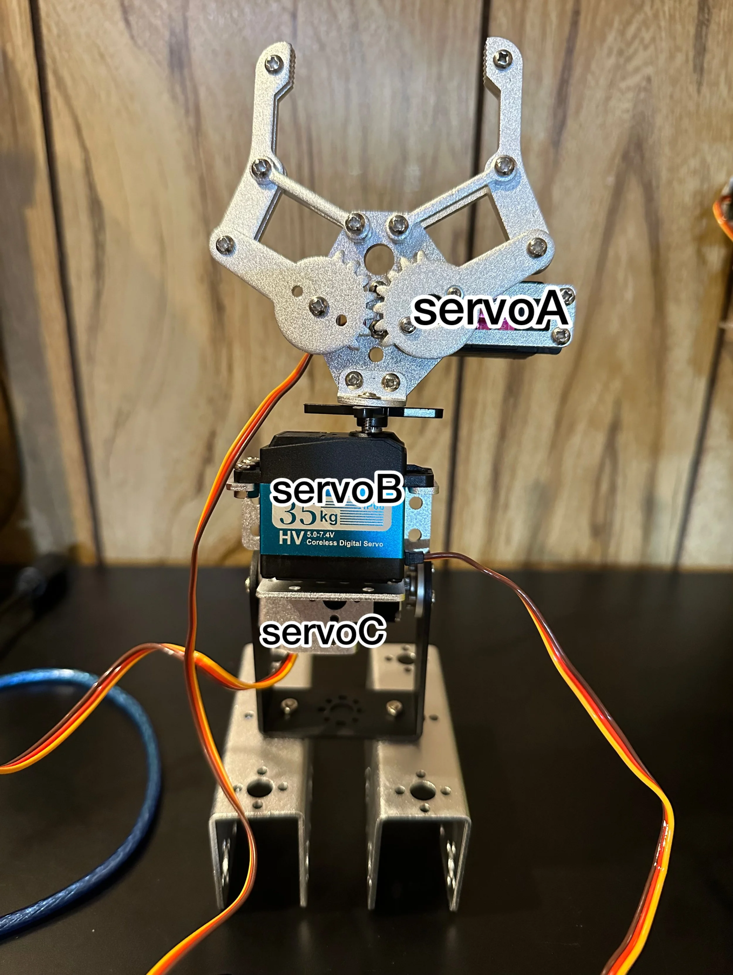
Note: I preassembled my robotic claw arm and my design software currently doesn’t include the frame parts, so I’ll explain where the servos go and how to connect them but my diagram will not show the frame itself. To make up for that, I’ll also provide images of the actual robotic arm that can be referenced for more help with assembly.
Since we’re using three servos, we’ll be able to control three joints. The first servo (servoA) will be connected to the claw piece itself and will control the opening and closing movement. The second servo (servoB) will be placed at the base of the claw and will control rotational movements. The third servo (servoC) will be at the base of the claw and will control flexion and extension of the claw.
Once you have your claw fully assembled, it’s time to connect the servos to the Arduino. To do that, we’ll start with servoA (or the claw servo). Connect the servo’s power wire to the power bus on the breadboard, the ground wire to the ground bus on the breadboard and the control wire can be connected to the 8 pin on the Arduino board. For servoB (also the rotational servo) we’ll repeat the same process but this time the control wire will be connected to the 9 pin. Finally, with servoC (the base servo), we’ll repeat that process and connect the control wire to the 10 pin on the Arduino board.
Now that you have all of your components connected, you can connect the Arduino’s GND and 5V supply to the breadboard by adding wires to those pins and by connecting the 5V to the power bus on the breadboard and the GND to the ground bus on the breadboard. You may also be using an external power supply to give the servos some extra power so that they’ll move so you’ll want to add your 16V 100uf capacitor to your breadboard between the servos and your battery/external power supply. You can refer to the following diagram for a bit more clarification.
With everything successfully connected, it’s time to start coding. For that, you’ll need to first download the Arduino IDE. After that, the first thing we’ll do is add the servo library to our sketch so that we can control our servos.
#include <Servo.h>
If you need to add the servo library, you can do so by clicking on the library tab in your IDE > typing “servo” into the search container and selecting the library. I recommend double checking that you have this library installed before moving on to the next step because it might save you a potential failed compilation later on.
Once you have the servo library added, the next step is to setup the buttons so that they can be easily referenced and paired with certain actions later on.
//Setup Buttons
const int buttonA = 2;
const int buttonB = 3;
const int buttonC = 4;
const int buttonD = 5;
const int buttonE = 6;
const int buttonF = 7;

//Variable to Store Button States
int buttonAState;
int buttonBState;
int buttonCState;
int buttonDState;
int buttonEState;
int buttonFState;

//Declare Servos
Servo servoA; //Claw Servo
Servo servoB; //Rotation Servo
Servo servoC; //Flexion/Extension Servo

//Variables to read/store servo positions and for incremental movement
int angle = 0;
int angleMove = 10; //Moves the servo in 10 degree increments
int angleMinus = -10; //Moves the servo in -10 degree increments
The first step in this is to connect each button with its corresponding pin in the code, then create variables to store the current state of each button (pressed vs not pressed).
After that, we declare the servos and store then in variables so they can be connected to the push buttons. The names I’ve chosen (servoA, servoB, servoC) are my own and don’t have to be exact, feel free to be more creative with your variable names.
Next you’ll want to create variables for the current position of the servos and to allow for incremental movement vs needing to move to specific angles. The angleMove adds 10 degrees to the servo’s current position while the button is being held and the angleMinus subtracts 10 degrees from the servo’s current position while the button is being held.
After setting up the variables, the next step is to go into the void setup(), attach the servos and set the buttons as inputs.
void setup() {

  //Connect servos to corresponding pins
  servoA.attach(8);
  servoB.attach(9);
  servoC.attach(10);

  //Set buttons as inputs
  pinMode(buttonA, INPUT);
  pinMode(buttonB, INPUT);
  pinMode(buttonC, INPUT);
  pinMode(buttonD, INPUT);
  pinMode(buttonE, INPUT);
  pinMode(buttonF, INPUT);

}
Once that’s done, the final part is to go into the void loop() and add the final bit of code. Here, you’re telling the variables you previously created for the buttons to constantly read the button’s current status and you’re adding if statements which tell your servos to respond to the buttons when they’re pushed.
void loop() {

  //Read button states and store them in variables
  buttonAState = digitalRead(buttonA);
  buttonBState = digitalRead(buttonB);
  buttonCState = digitalRead(buttonC);
  buttonDState = digitalRead(buttonD);
  buttonEState = digitalRead(buttonE);
  buttonFState = digitalRead(buttonF);

  //To open and close the claw
  if(buttonAState == HIGH) {
    servoA.write(angle = angle + angleMove);
    delay(100);
  }

  if (buttonBState == HIGH) {
    servoA.write(angle = angle + angleMinus);
    delay(100);
  }

  //To rotate the claw
  if(buttonCState == HIGH) {
    servoB.write(angle = angle + angleMove);
    delay(100);
  }
  if (buttonDState == HIGH) {
    servoB.write(angle = angle + angleMinus);
    delay(100);
  }

  //To raise and lower the claw
  if(buttonEState == HIGH) {
    servoC.write(angle = angle + angleMove);
    delay(100);
  }

  if(buttonFState == HIGH) {
    servoC.write(angle = angle + angleMinus);
    delay(100);
  }

}
From there, all that’s left to do is to connect your USB cable to your Arduino and your computer, upload the code and test out the device.
And with that, you’ve successfully completed your very own button controlled robotic claw arm. See what else you can do with servos and/or your robotic claw arm from here.
Remember, the only real limits to what you can do are your imagination, your drive to succeed and possibly your budget.
Note: Once the code is compiled and uploaded, you may need to connect an external battery supply so that your servos have enough power for all of the movements. Just be sure to follow all safety recommendations if you’re using batteries and don’t add them if you’re not sure you can do so safely.
If you get stuck and/or you’re having issues getting your sketch to compile, you can refer to the completed code for this project below.
//トラビス
#include <Servo.h>

//Setup Buttons
const int buttonA = 2;
const int buttonB = 3;
const int buttonC = 4;
const int buttonD = 5;
const int buttonE = 6;
const int buttonF = 7;

//Variable to Store Button States
int buttonAState;
int buttonBState;
int buttonCState;
int buttonDState;
int buttonEState;
int buttonFState;

//Declare Servos
Servo servoA; //Claw Servo
Servo servoB; //Rotation Servo
Servo servoC; //Flexion/Extension Servo

//Variables to read/store servo positions and for incremental movement
int angle = 0;
int angleMove = 10; //Moves the servo in 10 degree increments
int angleMinus = -10; //Moves the servo in -10 degree increments


void setup() {

  //Connect servos to corresponding pins
  servoA.attach(8);
  servoB.attach(9);
  servoC.attach(10);

  //Set buttons as inputs
  pinMode(buttonA, INPUT);
  pinMode(buttonB, INPUT);
  pinMode(buttonC, INPUT);
  pinMode(buttonD, INPUT);
  pinMode(buttonE, INPUT);
  pinMode(buttonF, INPUT);

}

void loop() {

  //Read button states and store them in variables
  buttonAState = digitalRead(buttonA);
  buttonBState = digitalRead(buttonB);
  buttonCState = digitalRead(buttonC);
  buttonDState = digitalRead(buttonD);
  buttonEState = digitalRead(buttonE);
  buttonFState = digitalRead(buttonF);

  //To open and close the claw
  if(buttonAState == HIGH) {
    servoA.write(angle = angle + angleMove);
    delay(100);
  }

  if (buttonBState == HIGH) {
    servoA.write(angle = angle + angleMinus);
    delay(100);
  }

  //To rotate the claw
  if(buttonCState == HIGH) {
    servoB.write(angle = angle + angleMove);
    delay(100);
  }
  if (buttonDState == HIGH) {
    servoB.write(angle = angle + angleMinus);
    delay(100);
  }

  //To raise and lower the claw
  if(buttonEState == HIGH) {
    servoC.write(angle = angle + angleMove);
    delay(100);
  }

  if(buttonFState == HIGH) {
    servoC.write(angle = angle + angleMinus);
    delay(100);
  }

}


